W4-Project1-Gravity

Initial thought and sketch
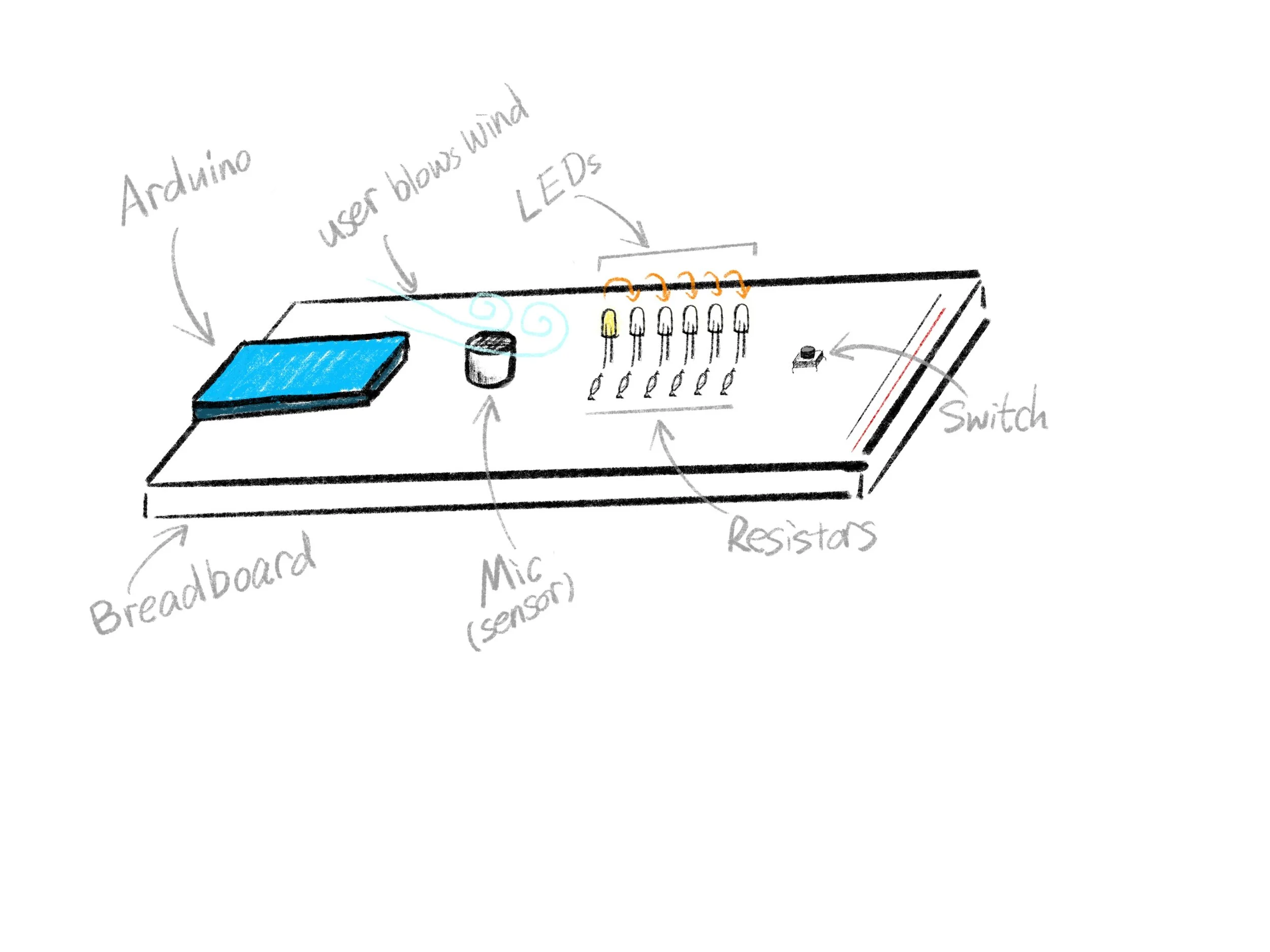
For the first project, I want to do a project that builds a connection between the physical and digital spaces. It contains a sensor that can measure wind blowing into it, an array of LED lights, and switch to reset the program. After resting the program, the first LED will light up. Users can blow into the sensor, and the following light will turn on while the previous one goes off. The interaction is blowing the "light ball" forward. I thought of using a microphone as the sensor and measuring the volume when the user blows the wind. Larger volume means stronger wind so that the light will move forward faster. I also want to set how much force is needed to light up each LED, adding a sense of weight and resistance to each LED.
Further planning and thinking before starting
I wanted to find a way to remove the switch, so there is no definitive ending and beginning in this piece. I searched for an intuitive explanation for lights to "come back" or relit when no interaction is happening. So I continued with the thought of blowing the imaginary ball. A natural way for a physical to come back is to have another force source on the other end to kick the ball back. Or, the ball can roll back itself with gravitational force if it is on a slope. Therefore, I developed the idea of till the board, so it can imply the gravity easily. To make the entire set complete and reasonable, I decided to build a snow forest hill. The interaction will be blowing the ball up the slope, and when the blowing paused, the snowball will roll back down the mountain.

CODE
Setting up the mic with Arduino and breadboard

I connected the mic the same way I attached the FSR and connected a LED to a digital output pin that supports analog output. I am not sure if it's the quality of the mic or my surroundings. The sensor value reading from the mic was very noisy. When no wind was blown into the mic, the reading stayed around 840, but when I started blowing wind, the reading varied from 1 to 1000. these huge unstable variations from readings make it hard to steadily develop a stable interaction between user blowing into the mic and controlling lights one by one.

What I came up with was to eliminate all reading below 840. When there's no input, the reading is around 840, so I considered anything below that as reading error. To make input from the mic even more precise and stable, I mapped inputs from 840 to 1000 to a 0 to 20 range. Another idea I developed to achieve what I want to do is to image all the lights are on an x-axis. The first one is on the origin, 0. I created a variable called accumulateValue, representing how far the user has blown on the axis. Each light has a predetermined range. The brightness goes up and down, and the light will go off if accumlateVlaue is out of its range. There's also a decremental mechanism for the accumulatValue to mimic falling down the hill. Lastly, I forced accumulateValue to set to 0 when it's negative, so it won't keep on decreasing when there's no input. Here is the code:
  //changing the accumulateValue
  //increment the accumulateValue with sensorInput.
  //change the rate of incrementing by changing what number times the Input
  if (sensorInput > 0) {
    accumulateValue += 2 * sensorInput;
  }
  //Decreasing the accumluate value for rolling down the hill
  else if (accumulateValue > 0) {
    accumulateValue -= 8 ;
  }
  //Keep the ball at 0 as its lowest point.
  else if (accumulateValue <= 0) {
    accumulateValue = 0;
  }
Coding lights behaviors
Except for the first light, each light has a similar behavior. The brightness of a LED will go from 0 to 255 to 0 within its range. I have a linear value, accumulateValue, that goes up or down. The challenge is how to convert that linear value to go up and down. I came to the idea of using cos and sin curves. Depends on the radiant, the result of cos or sin will vary from 1 to -1.

I first declared individual range called accumulate1, accumulate2, accumulate3, etc. And then using constrain to set up a range for each of them. Then map the range to radiants to be used in the cos and sin functions. Lastly, calculate the value of cos or sin, use that to determine the LED brightness. Additionally, I multiply the cos and sin values with a change rate, so I could control how fast each light is changing.
The code could be condensed and simplified, but I used the following code for testing and debugging.
  accumulate1 = constrain(accumulateValue, 0, 150);
  mappedCurve1 = map(accumulate1, 0, 150, 0, PI);
  curveInput1 = cos(mappedCurve1);
  ledValue1 += changeRate * curveInput1;
  ledValue1 = constrain(ledValue1, 0, 255);

  accumulate2 = constrain(accumulateValue, 200, 900);
  mappedCurve2 = map(accumulate2, 200, 900, -PI / 2, 3 * PI / 2);
  curveInput2 = sin(mappedCurve2);
  ledValue2 += changeRate * curveInput2;
  ledValue2 = constrain(ledValue2, 0, 255);

  accumulate3 = constrain(accumulateValue, 800, 1500);
  mappedCurve3 = map(accumulate3, 800, 1500, -PI / 2, 3 * PI / 2);
  curveInput3 = sin(mappedCurve3);
  ledValue3 += changeRate * curveInput3;
  ledValue3 = constrain(ledValue3, 0, 255);

  accumulate4 = constrain(accumulateValue, 1400, 2100);
  mappedCurve4 = map(accumulate4, 1400, 2100, -PI / 2, 3 * PI / 2);
  curveInput4 = sin(mappedCurve4);
  ledValue4 += changeRate * curveInput4;
  ledValue4 = constrain(ledValue4, 0, 255);

  accumulate5 = constrain(accumulateValue, 2000, 2700);
  mappedCurve5 = map(accumulate5, 2000, 2700, -PI / 2, 3 * PI / 2);
  curveInput5 = sin(mappedCurve5);
  ledValue5 += changeRate * curveInput5;
  ledValue5 = constrain(ledValue5, 0, 255);

  accumulate6 = constrain(accumulateValue, 2600, 3300);
  mappedCurve6 = map(accumulate6, 2600, 3300, -PI / 2, 3 * PI / 2);
  curveInput6 = sin(mappedCurve6);
  ledValue6 += changeRate * curveInput6;
  ledValue6 = constrain(ledValue6, 0, 255);
CRAFT
to be continued…