W1-The intro to intro to Prom
First time using a multimeter. Testing the voltage from the power supply. I think mine is a regulated one.

Setting up a breadboard
I made a DC power supply by wiring a female power supply head and connecting it to the DC power source.

I don’t have solid core hookup wires. I realized how messy it can get after setting up the board. I will order them now.

With the voltage regulator, the voltage is 5V. I measured with a multimeter

Connected the first LED to the board, and it worked.

Then on top of that setup, I added a button.

But then I realized that the resistor isn’t connected between the button and the LED as shown on the Schematic image, Figure 26. So I switched up a bit.

I then added the second LED. And found they worked even when I removed the anode word at the bottom ( on the right-hand side if you see in the image below)

I think the two wires at the bottom are not necessary for this circuit, so I removed both of them. I also cut the resistor shorter so it looks slightly nicer. I really need to buy those wires. The breadboard is hard to follow, especially if you want to check if the flow is correct or not.

Measured the voltage on the resistor and two LEDs.
0.8V on the resistor, and 2.48V on LEDs.
Added the third LED, but none of them light up. The voltage is not enough for three of them.

Changed the circuit to connect LEDs in parallel

Measured the amperage. I firstly used 20A Max one, didn’t get any reading. Then switched to mA/uA one, and got 0.05mA
Connecting a Potentiometer
I don’t know how to solder, so I connected the potentiometer on the breadboard and wired each point of the pot with the breadboard. It worked

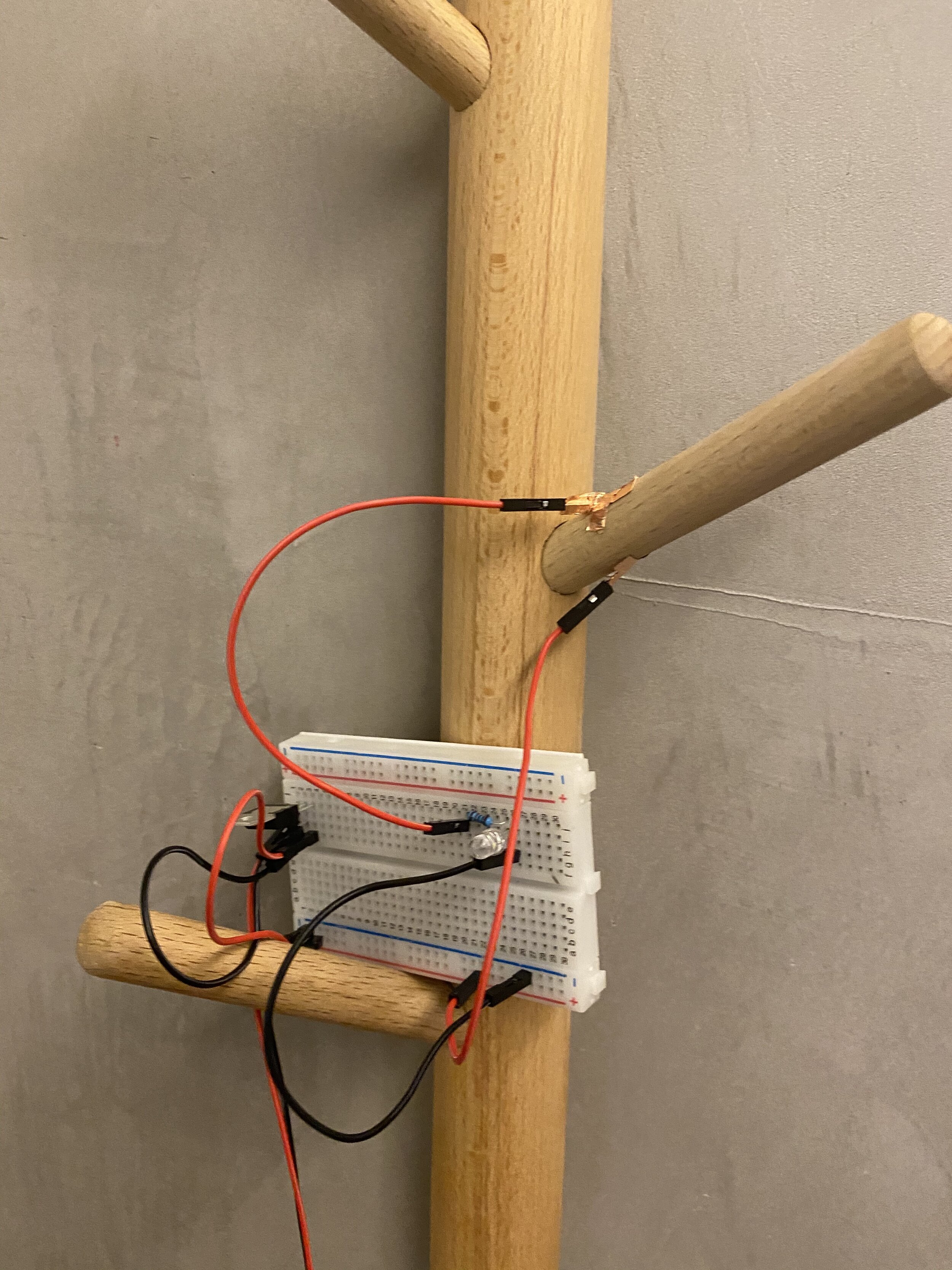
Creative Switch
For the creative switch, I made a simple circuit first to try out if the connection works. I used two wires taped with copper tape on one end as a simple demo of a switch. When they touch, the light will go on.

The idea of my switch is from looking for key in my room all the time. If there can be an indicator that can tell me if the key is on the hanger or not will be a great help for me. The metal ring on the key fits perfectly on the hanger, and it can be used as a conductor as well. I taped the two wires on top and bottom of a hanger. When the key ring slides in, it will connect the two wires. Thus closed the circuit and turned on the light.